Catching Up, pt2

It has been a few years now, and I’ve decided to dedicate some time this year to making progress on this project. So, let’s jump right in to where we left off!

V6gVk2Q - Imgur

I took a trip at the end of the last post I made here out to Summit Racing to grab some of the remaining engine and chassis parts to get closer to having a rolling chassis with an engine in it.

bTGE1Lu - Imgur

Here we see my car loaded up with a T56 transmission and a bunch of AN fittings, a flywheel, clutch, water pump, and some other misc parts.

GSbV4qM - Imgur

Transmission in the box, no bellhousing attached yet. This is a T56 Magnum, part number TUET-11012 for the higher ratios, hopefully helping me keep the power useable in this very light car.

gyohSO6 - Imgur

Flywheel attached, and close to being ready to go into the frame.

Db6SwLP - Imgur

Clutch bolted to the flywheel temporarily. I’ll be taking this back apart to swap those pressure plate bolts to some ARP ones that were in the mail at the time, but I was excited to get the drivetrain into the car.

WzAjRYz - Imgur

Getting the engine situated into the frame while still on the build cart, Grant helping line up the transmission mount.

k6jr2Nj - Imgur

Fully situated! Getting ready here to remove the engine hoist from the engine and let the car support the weight for the first time. Also a decent shot of the steering box and inboard front coilovers.

And here we are, for the first time seen with the drivetrain mostly in the car! Headers are attached, though they are not fit quite right and the mufflers won’t clear the bodywork as it is.

That is it for this post, look out here in another couple years for another update on the progress I’ve made, and progress I will be making!

Catching Up

It has definitely been a while since I made an update here. During that time, my daily driver Ford broke, twice, and that took me quite a bit of time to deal with. I also moved to another house, where I should have fewer problems with an HOA regarding working on my cars. There has been incremental progress, however, so here are some pictures of that.

IMG_0550

Here you can see the block prepared to have one of the heads put on it. Before I got this far I realized I had head studs from a Gen III LS block and had to get some for a Gen IV block like mine. This has the lifters installed in the valley, settled in place with the lifter trays, and the head gasket is resting on the studs.

IMG_0551

In this picture, both heads are bolted down and torqued to spec on the block. Still missing the valley cover, rocker arms, pushrods, and valve covers, but it looks mostly like an engine at this point.

IMG_0552

At this point the pushrods are in, rocker arms are bolted down, and the engine is ready for the valve covers to be bolted in place.

IMG_0558

Skipping ahead a couple of days, and the valve covers are attached, along with the valley cover, intake manifold, and the fancy red anodized fuel rails and fuel injectors. This is mostly temporary, in this car that black plastic intake manifold and the red rails will be facing towards the back of the engine, but first I need to make some modifications to the valley cover that they sit on. That work will be happening tomorrow.

IMG_0696

I also spent one day about 3 weeks ago at the shop where the frame is sitting, to test fit the suspension after the frame modifications. Here you can see the mocked up passenger’s side rear suspension, still missing a toe link to prevent the aluminum spindle in the center of the frame from rotating side to side.

IMG_0698

Here is a shot of the front passenger’s side suspension mocked up, also without steering at this point. Everything is loosely attached at best still, since it will all be coming back apart soon to be powder coated.

IMG_0707

This picture brings us to today. Here you can see the front and rear suspension in place, this time with steering and adjustable toe link. You can also make out some minor progress on mounting brake and clutch pedals at this point.

IMG_0711

And here is a blurry picture of the front suspension with a brake caliper mounted. Again, everything will be coming back off the car to be powder coated before final assembly.

Now we’re all caught up, and I will be back out at the shop tomorrow, so there should be more to come soon.


Engine and Roll Cage progress

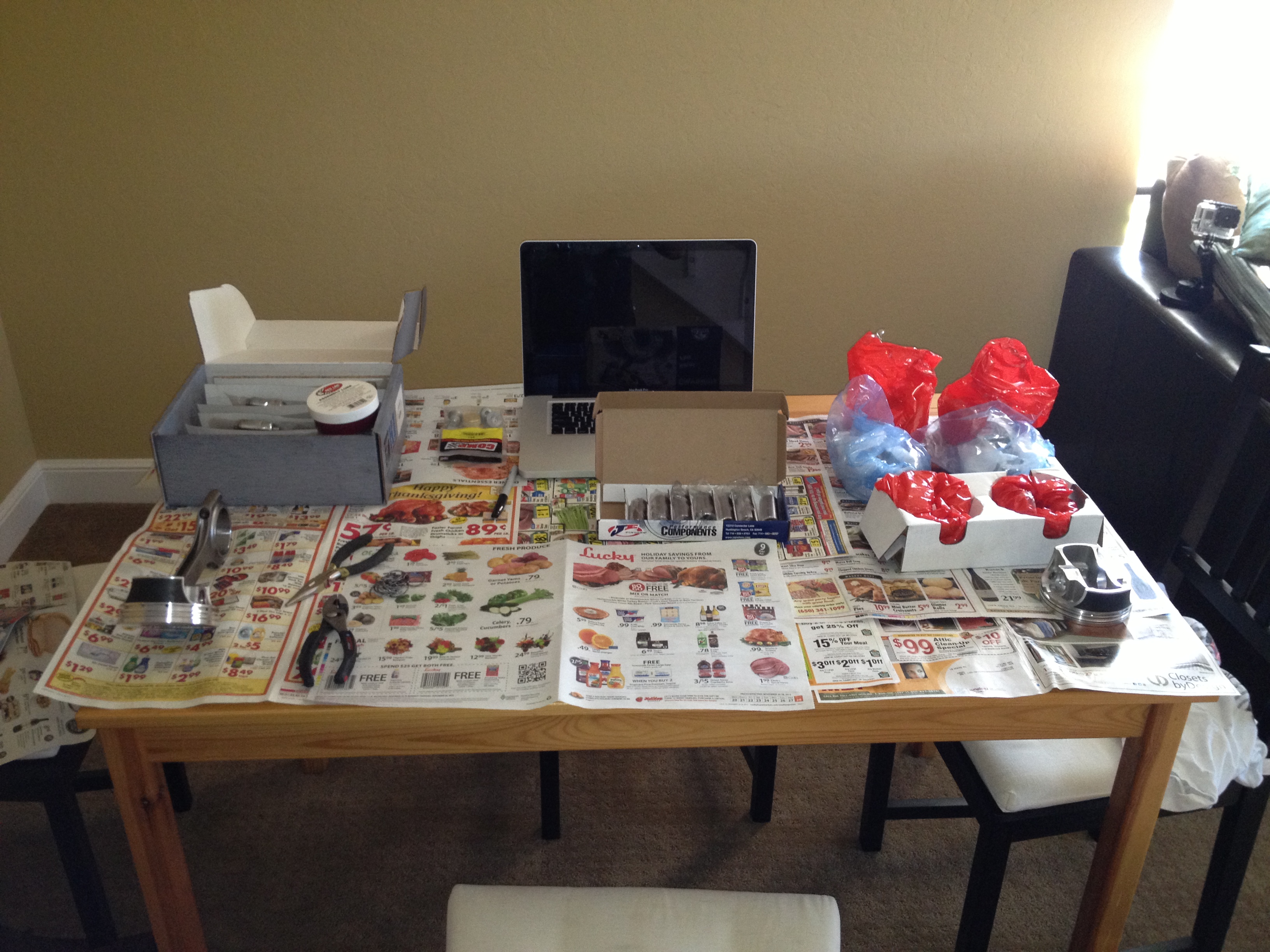
Over the past few weeks I’ve been making very incremental progress on the engine build, trying to scrounge up all of the various small pieces and tools required. At this point it probably would’ve been worth my time to go buy a junked engine just to use for various bolts, spacers, and whatever else rather than wait a few days at a time for the next part I need. Diving right in to the details and photos for that, here we go.

We start with the cam:

Image


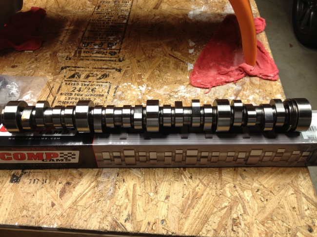
This is a relatively mild cam, only providing about 0.55″ of valve lift in a stock set up. My valvetrain being what it is, this ends up about 10% higher, and it should make for some pretty decent high-RPM power. The first step was to clean and grease the cam lobes, leaving #1 and #3 clean for use in testing Piston-to-Valve clearance later.

Image


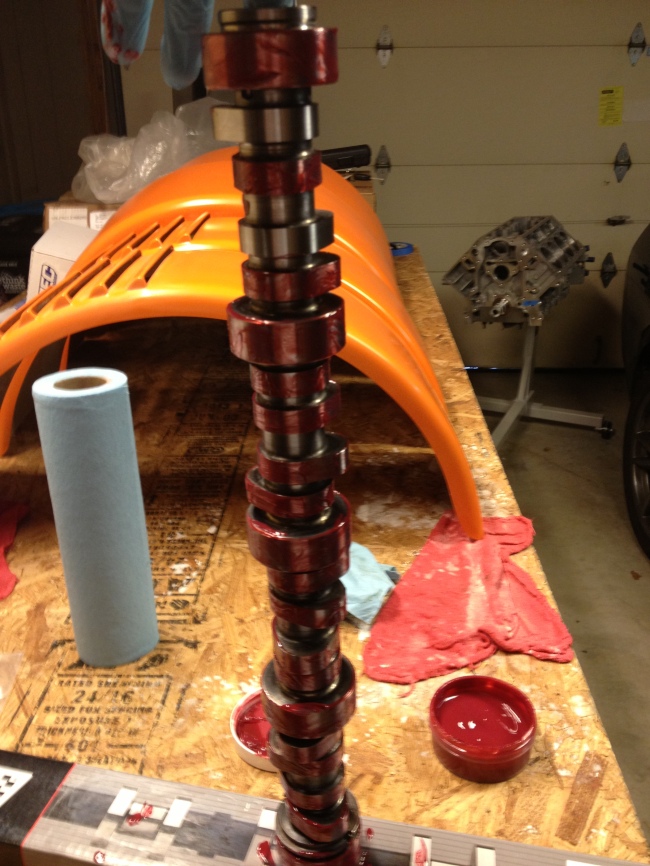
Next up, very gently the camshaft was placed in the engine, to wind up sitting on the camshaft bearings.

Image

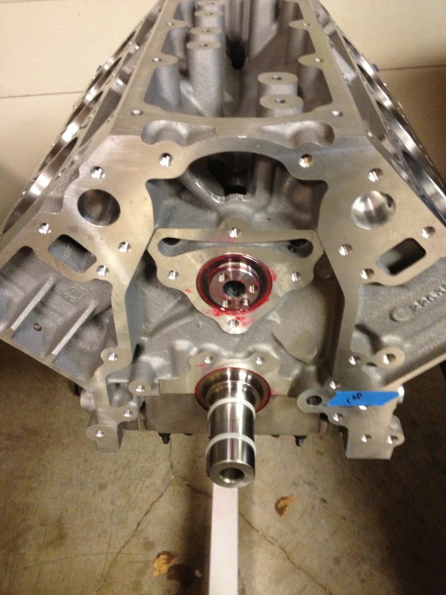
At this point one of my delays took place, while I ordered a cam thrust plate and bolts that I had assumed were part of the front main cover kit I had. I decided since I was making an order to go ahead and get the oil pan, windage tray, oil dipstick, head gaskets, and a camshaft degree checking kit as well. I ended up with a Holley oil pan with internal baffles that should be adequate for prevent oil starvation while cornering. Unfortunately the vendor I would’ve preferred to use doesn’t sell a suitable oil pan, but this will do nicely.

Once I got the order in, I continued by bolting down the cam. I was a bit surprised to find that these bolts required a T40 bit, and I had to dig around for quite a while to find one.

Image


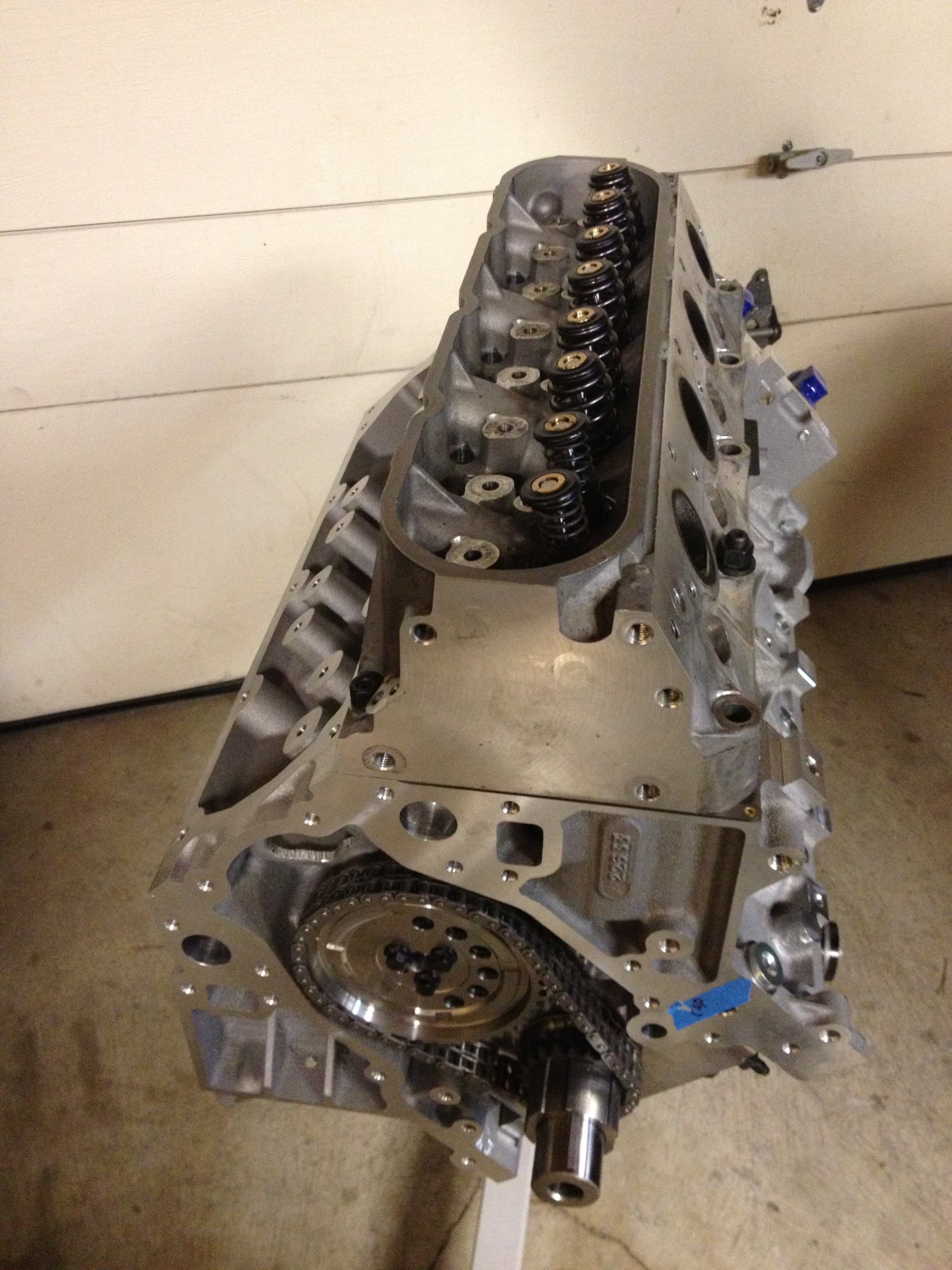
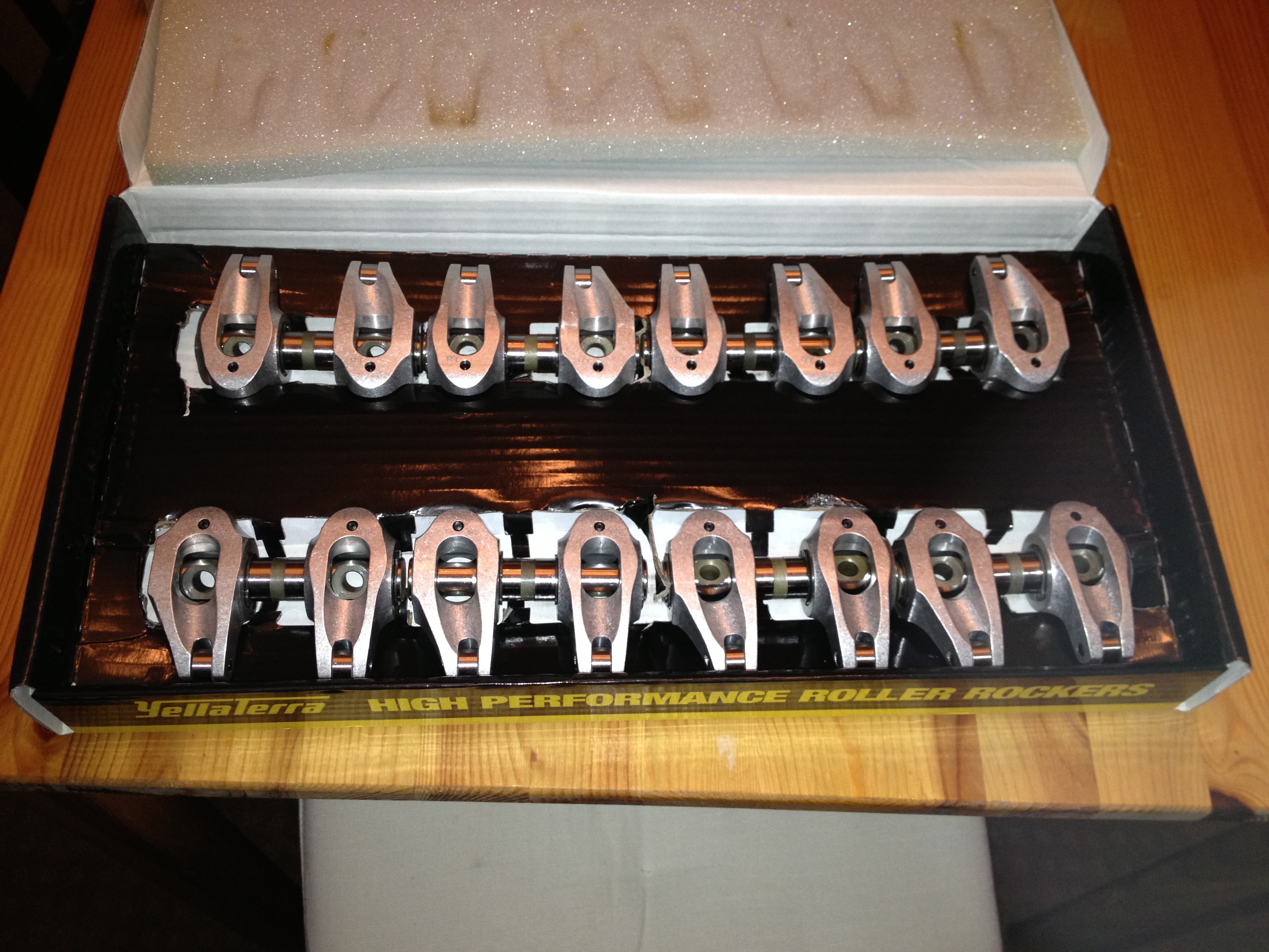
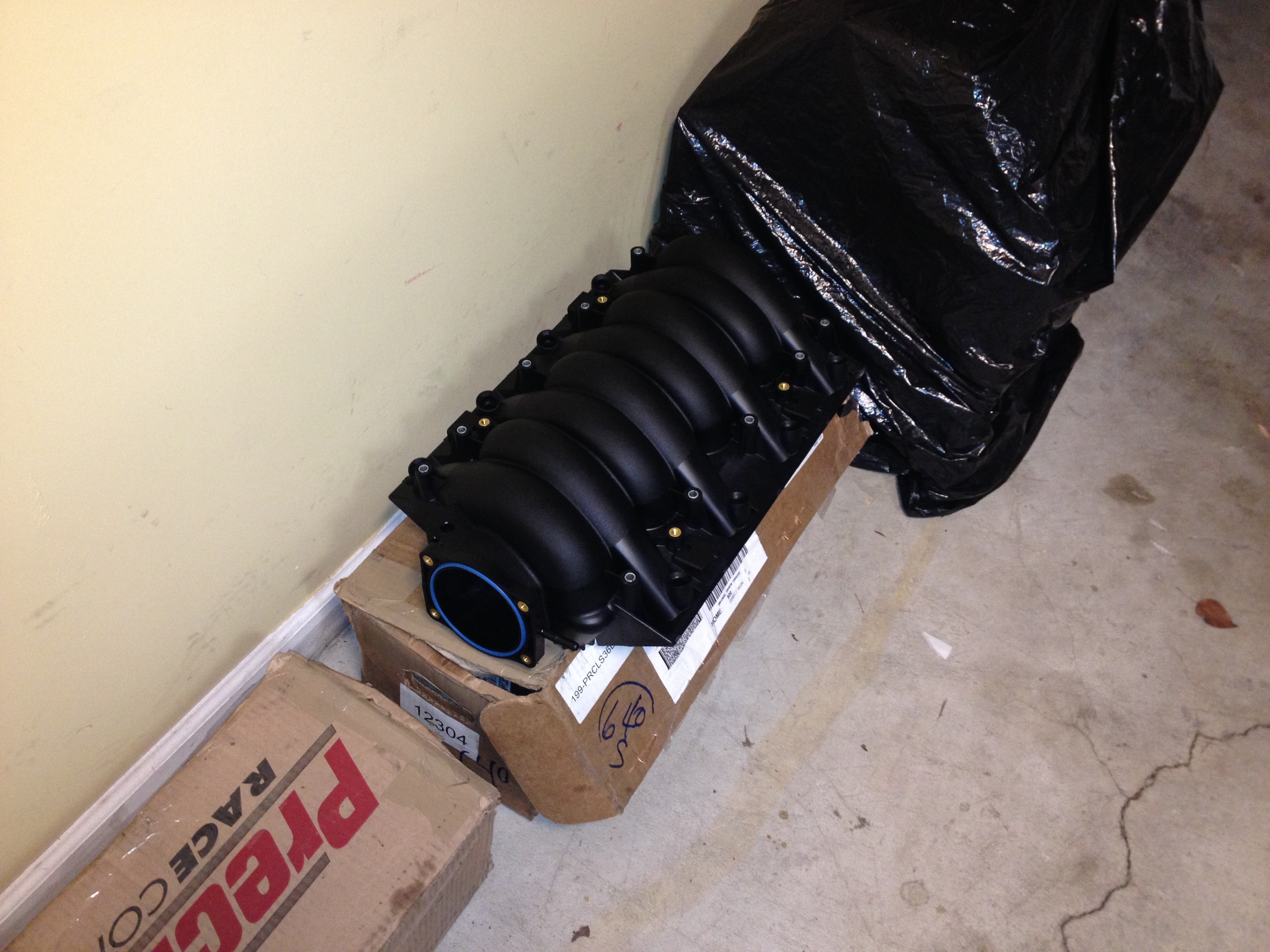
Next up, I started working on replacing the valvesprings in the heads. The heads came to me with about 800 miles on them, with some nice aftermarket double springs, but I want to try and keep the valvetrain as light as possible, and with the added stroke in the crankshaft won’t be turning this thing much faster than a stock one would anyways. So I replaced the existing springs with some high rate single beehive springs.

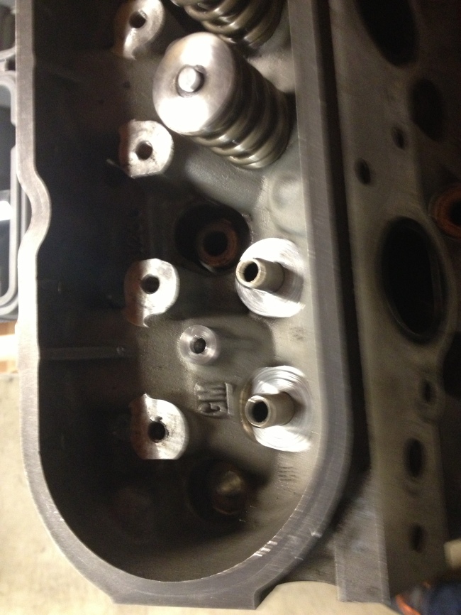
At first I thought this would be a simple matter of just swapping the springs using a spring compressor. In this picture you can see one of the old springs removed, and the spring seat it was sitting on.Image


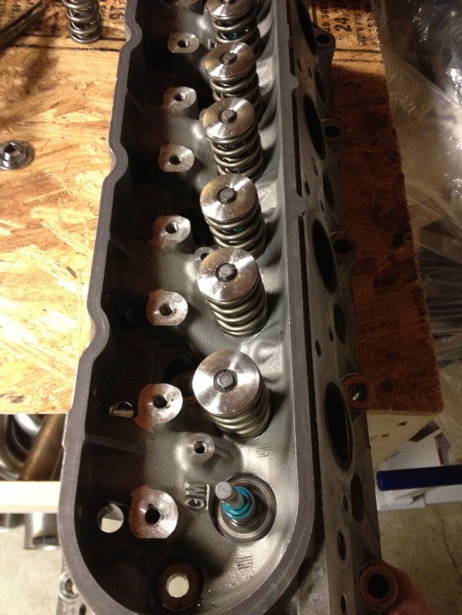
These seats turned out to be a problem, as well as the locks and retainers. I ordered all new valvespring hardware once I realized this, except for valve stem seals(that teal bit in the picture above), and put the valvespring project on hold until those arrived again.

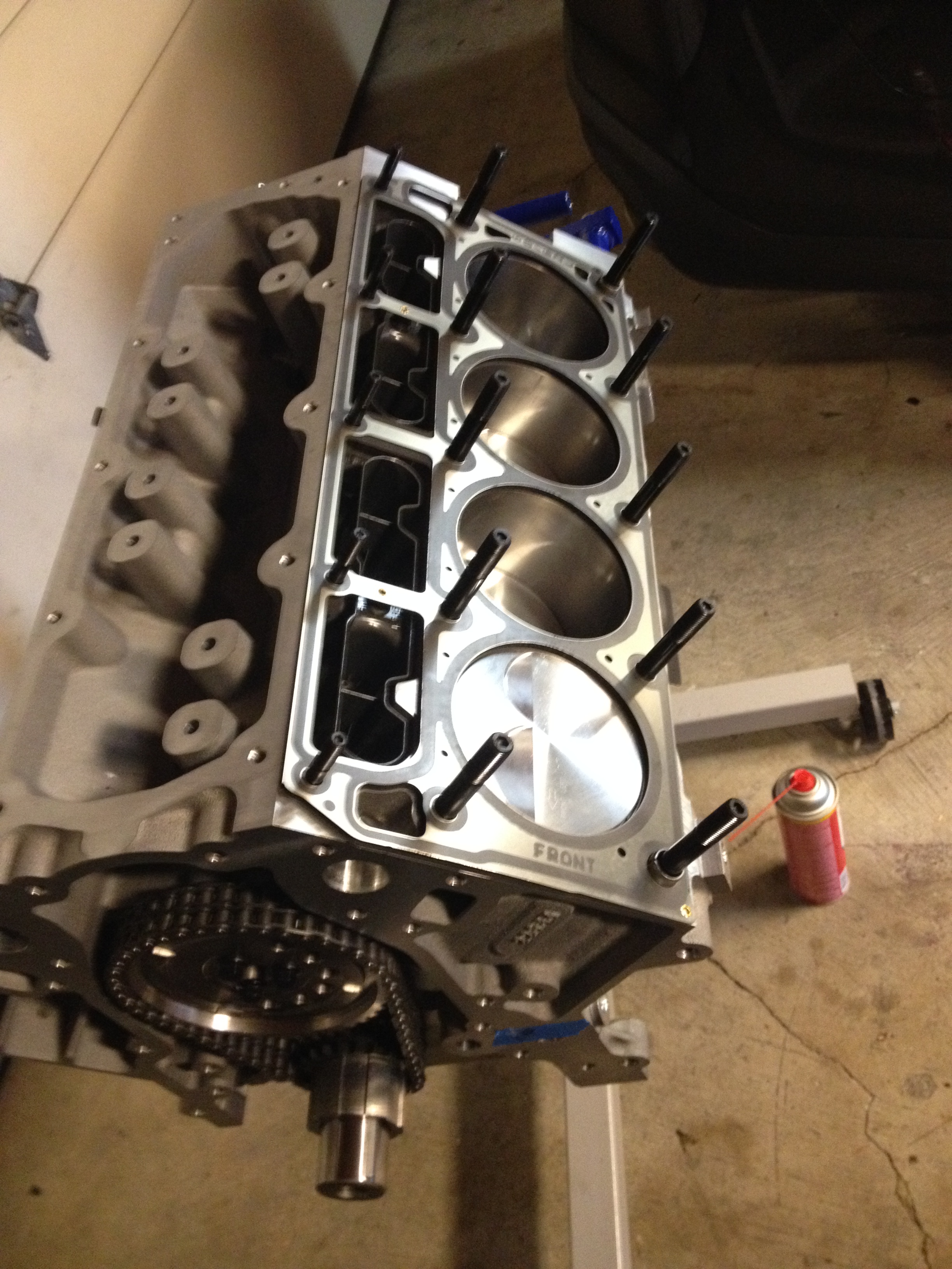
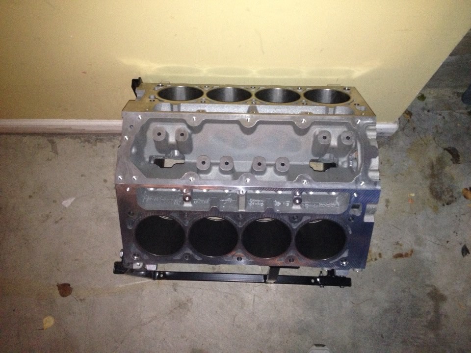
In the mean time, I got all of the block coolant plugs and the oil restrictor, and put those in the block. One of the main coolant plugs takes a 17mm Allen wrench to turn, which no hardware store stocks, and so I was stuck on this front until one arrived as well.

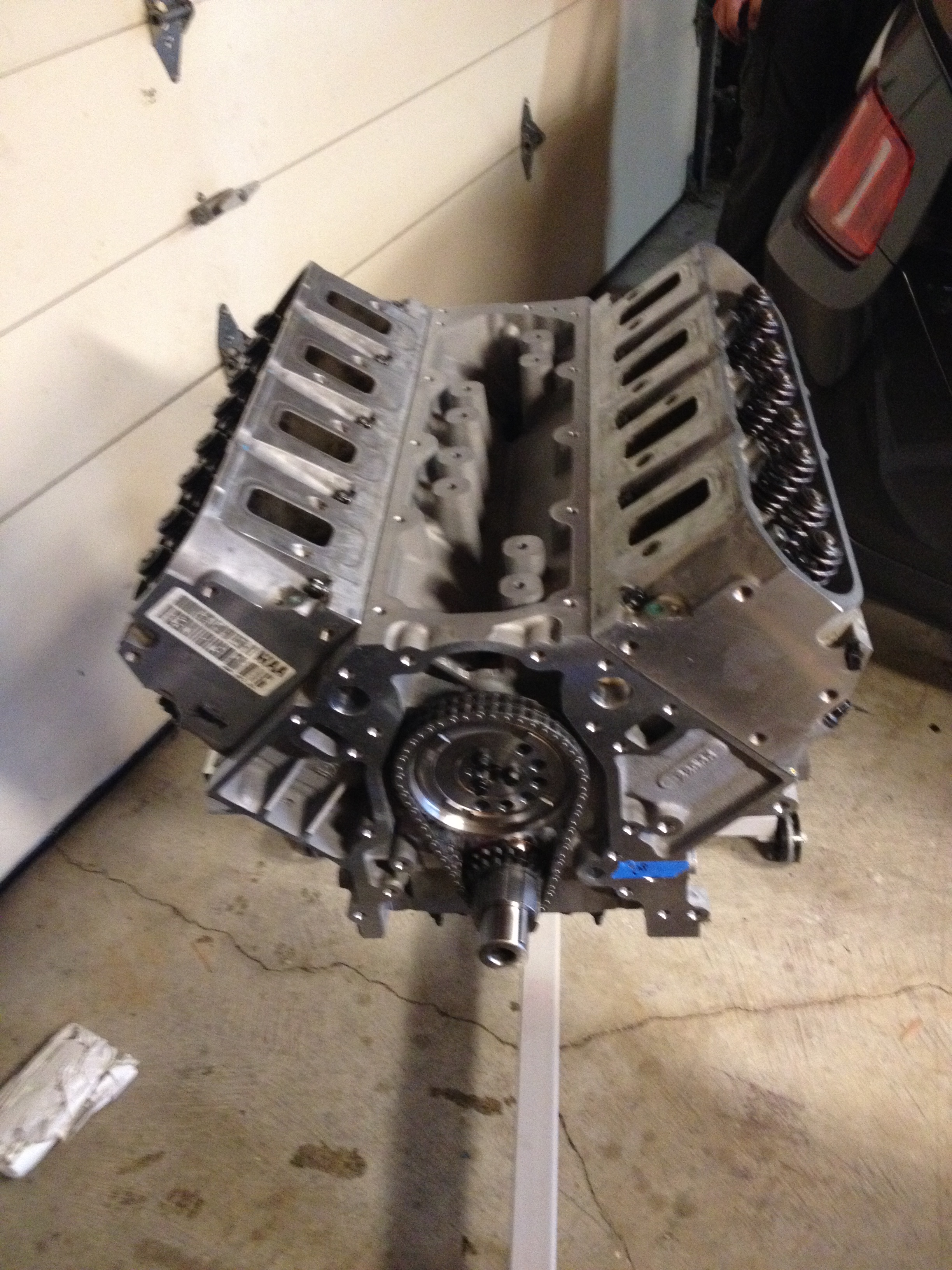
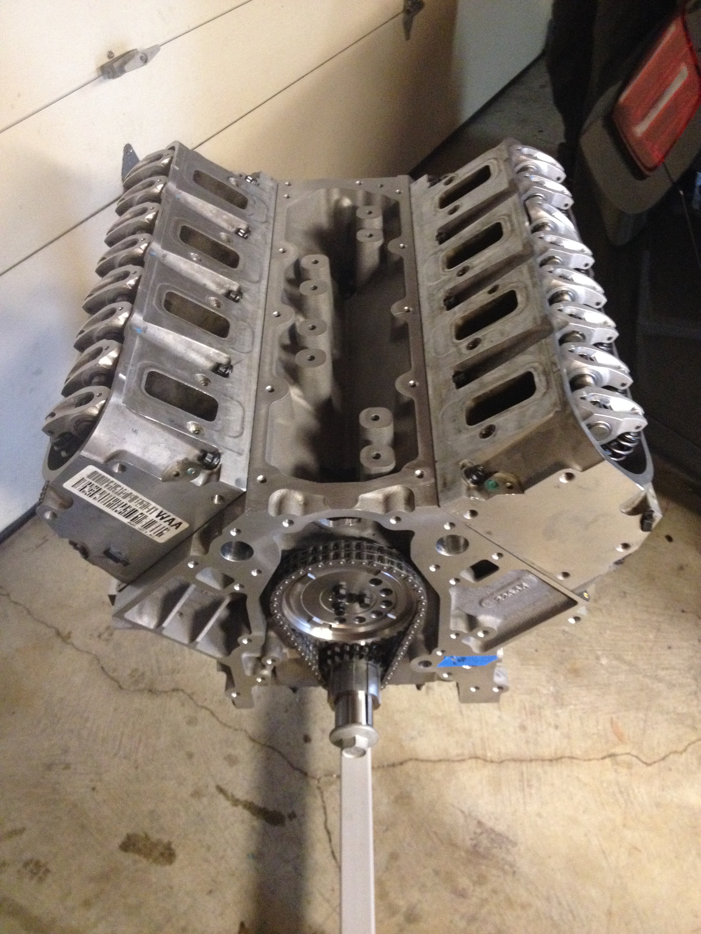
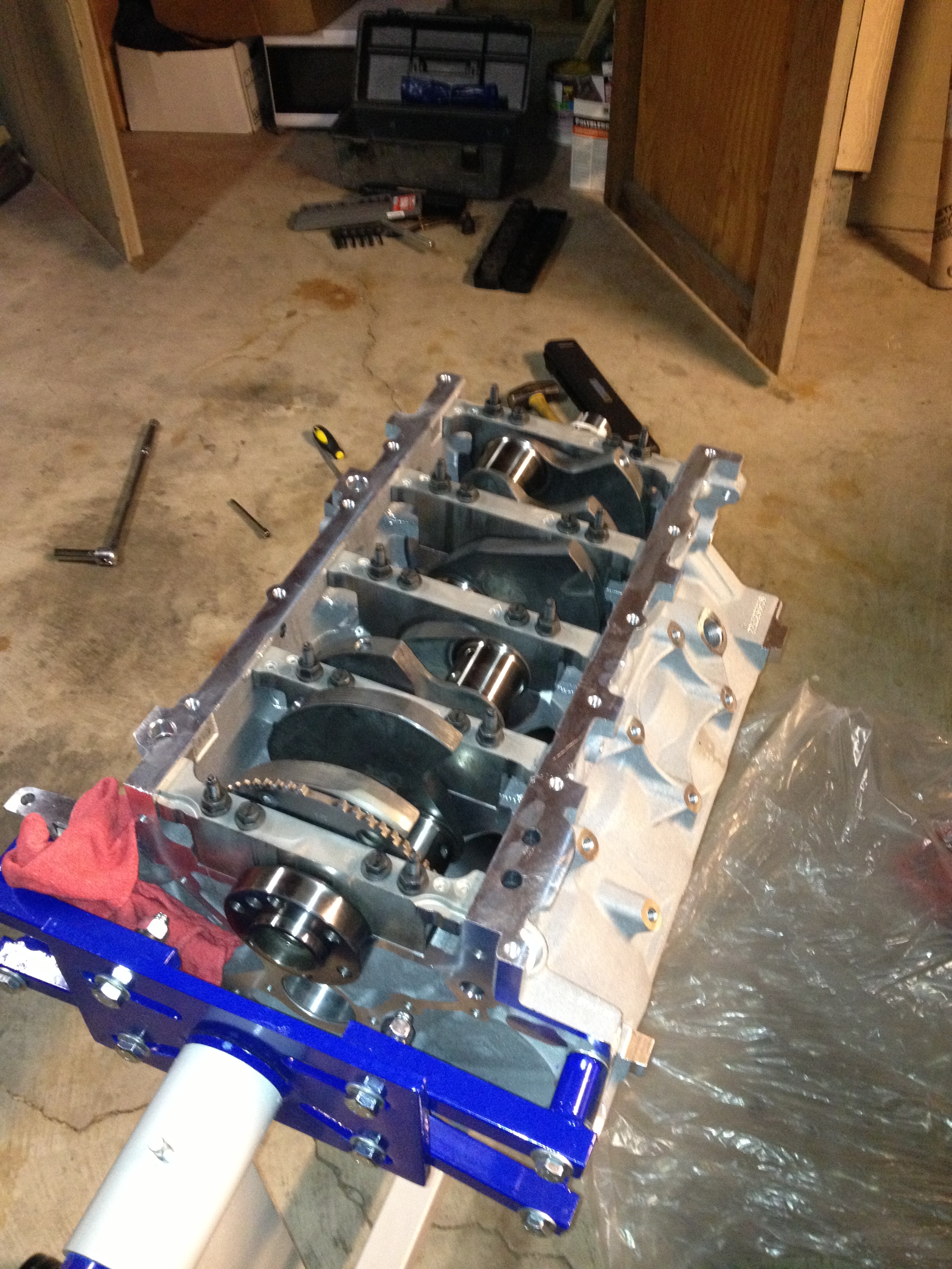
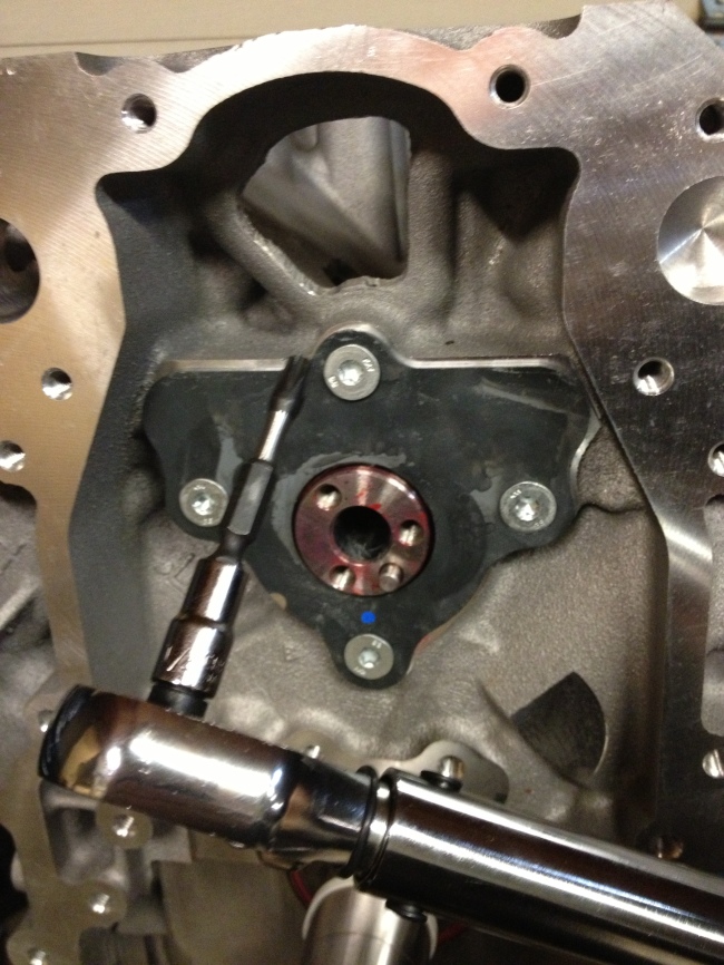
Being stuck now on two projects, I moved on to the timing set for the cam, and the timing gear and oil pump gear on the crankshaft.

Image


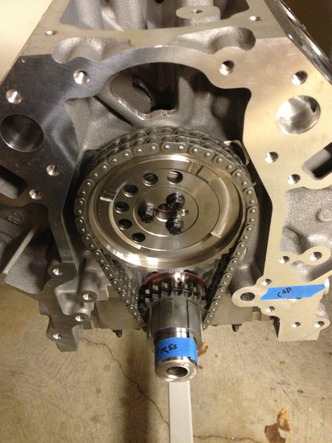
The timing set is a Comp Cams adjustable double timing set, and it was quite a pain to install. As you can see in the picture there, I had a note to myself to one day finish pressing the gears onto the crankshaft. These gears can’t be pounded on with a hammer, since the crankshaft itself sits directly on the main bearings. I ended up buying 3 different length bolts, a stack of various sizes of washers, some 1-1/2″ electrical conduit, and a 2″ diameter section of steel pipe to get them pressed all the way on. It was basically like playing stackable pipe Tetris, except each turn you have to unbolt a giant bolt.

That thankfully accomplished, I needed to be able to check the camshaft timing and the piston-to-valve clearance, so I converted some cheap hydraulic lifters into solid lifters to measure with.

Image


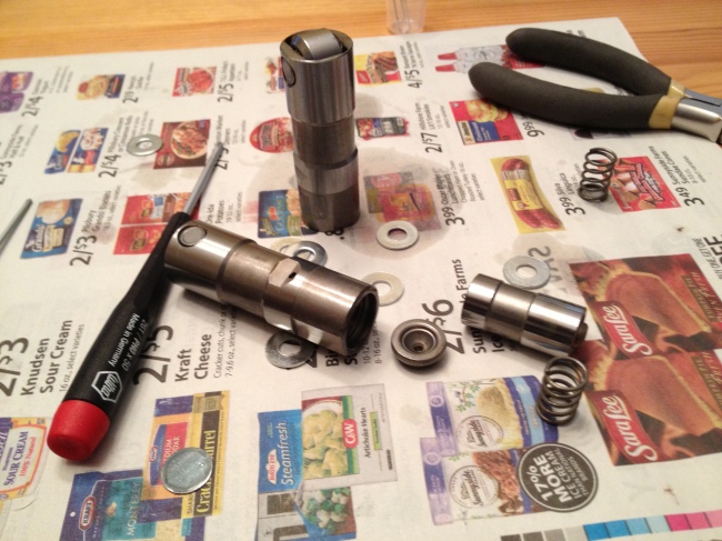
To do this, start by removing the retaining clip/spring(it helps if you aim this at your eyes and don’t wear protective glasses). Next, remove the plunger, seen here on the right, and spill all the oil on yourself. Finally, replace the plunger, add a washer or two as a spacer, leave the spring out, and put the retaining clip you shot at yourself earlier back in, if you can find it.

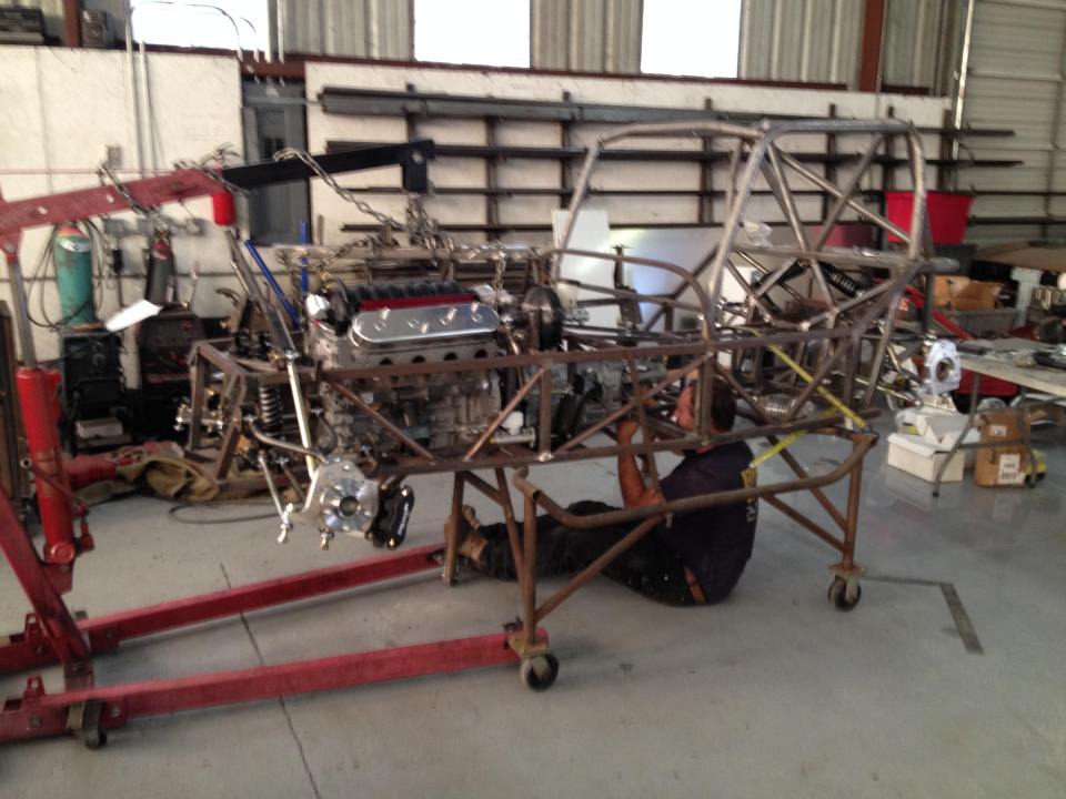
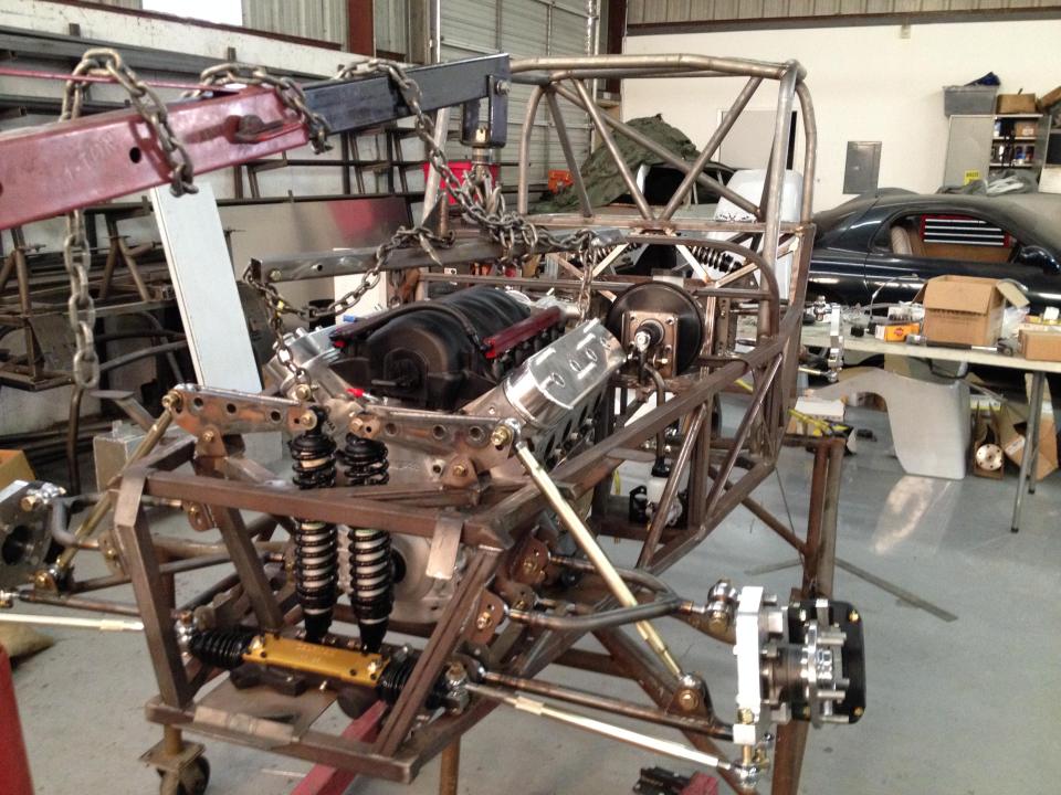
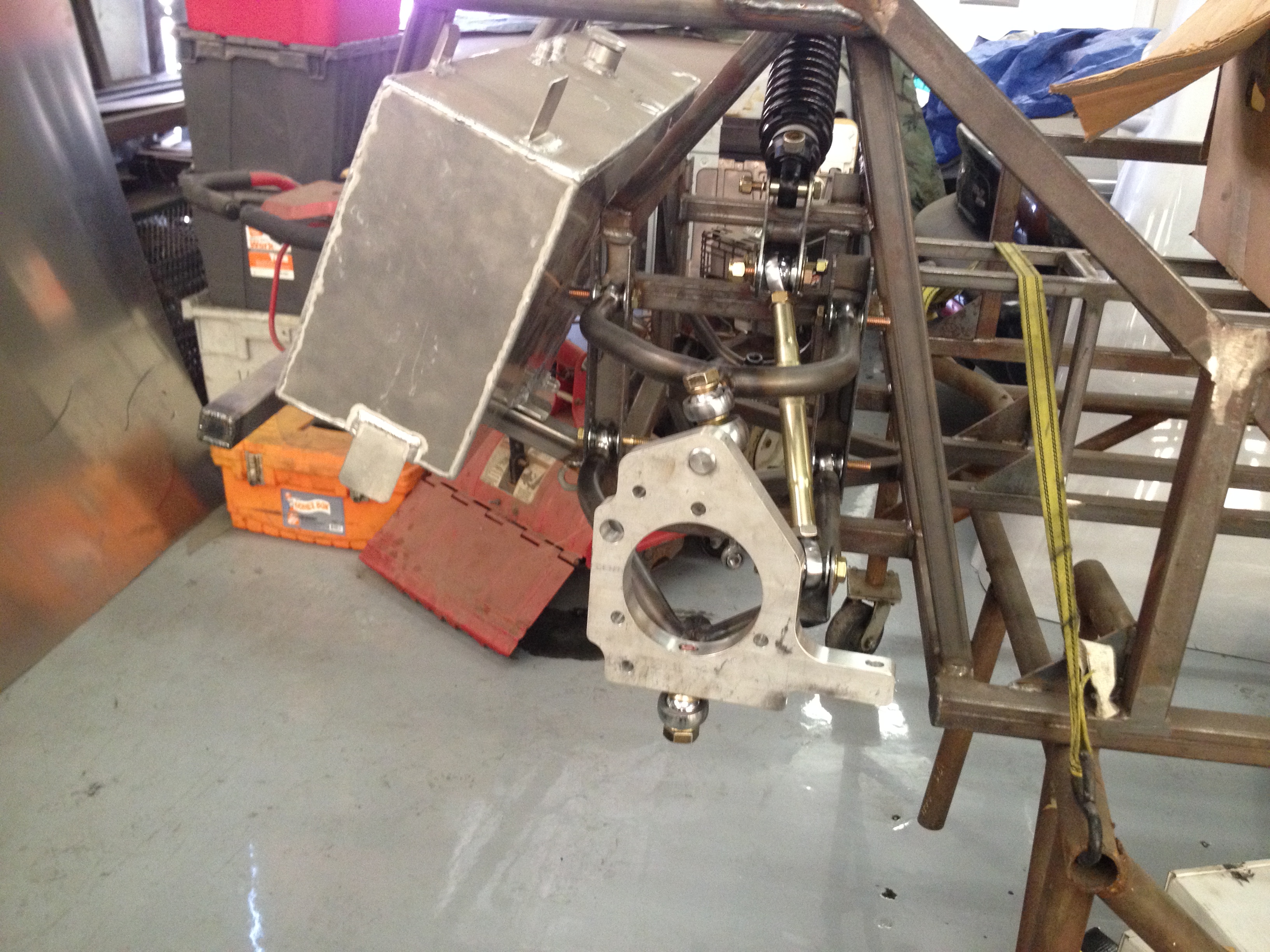
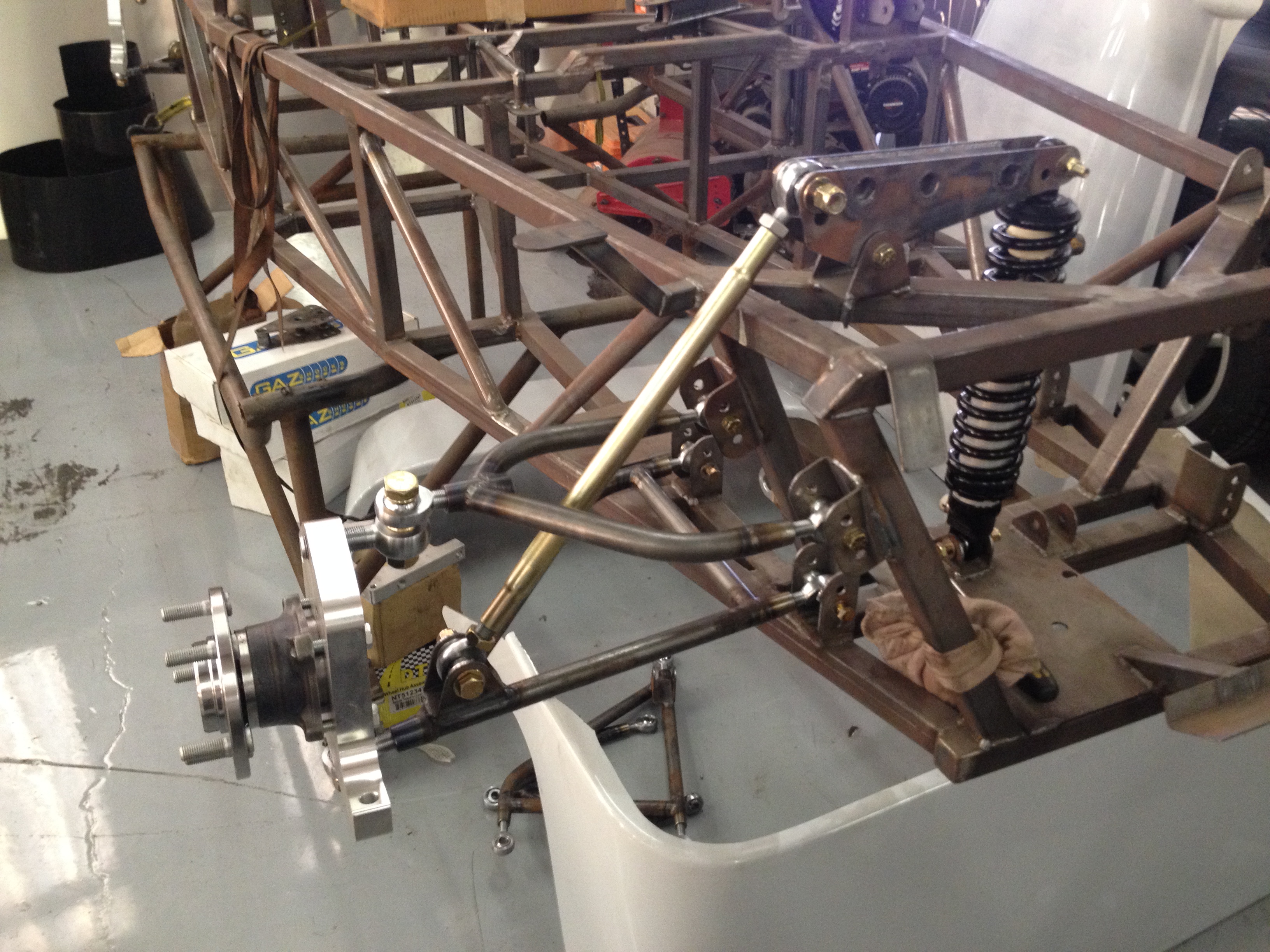
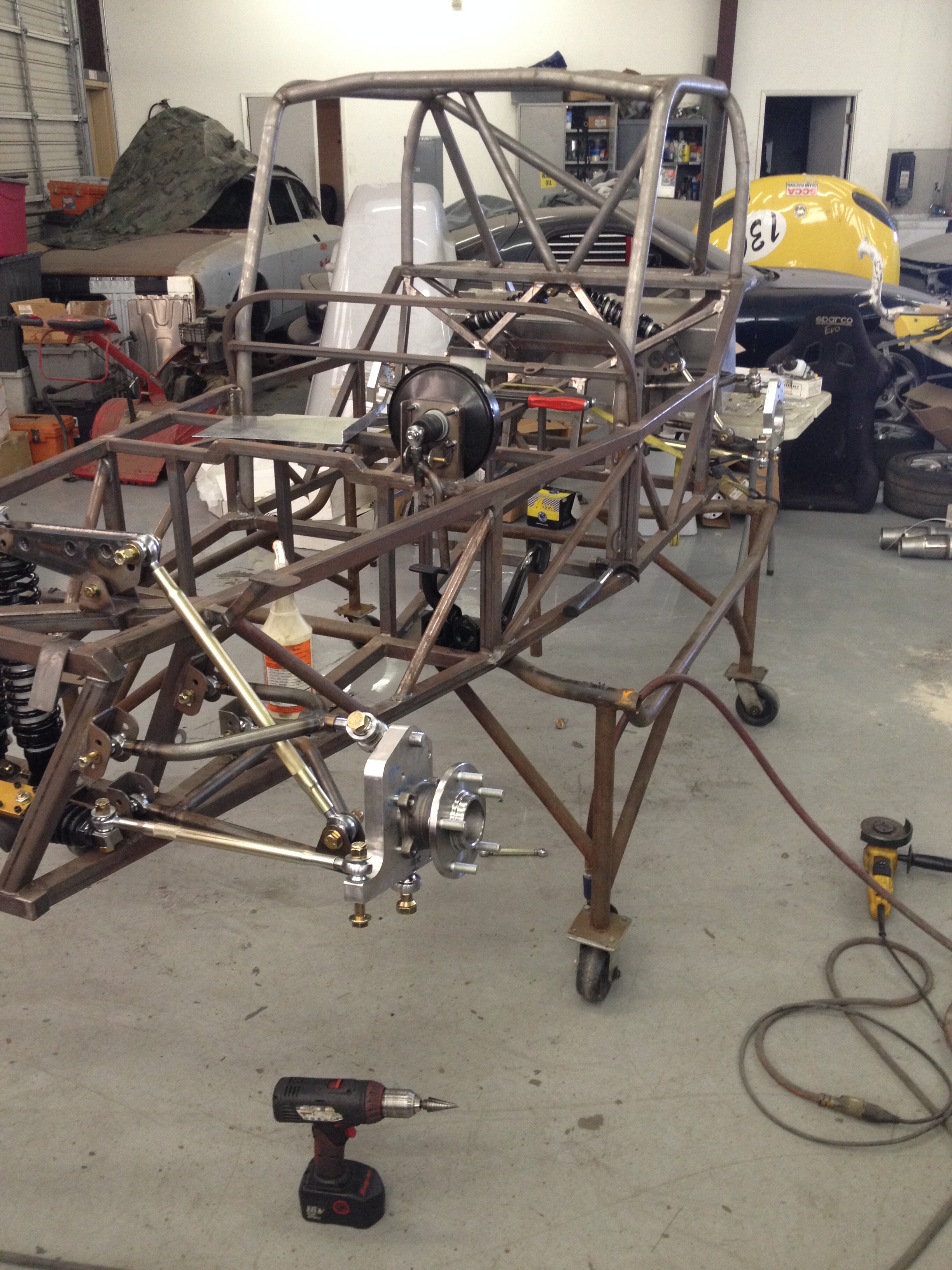
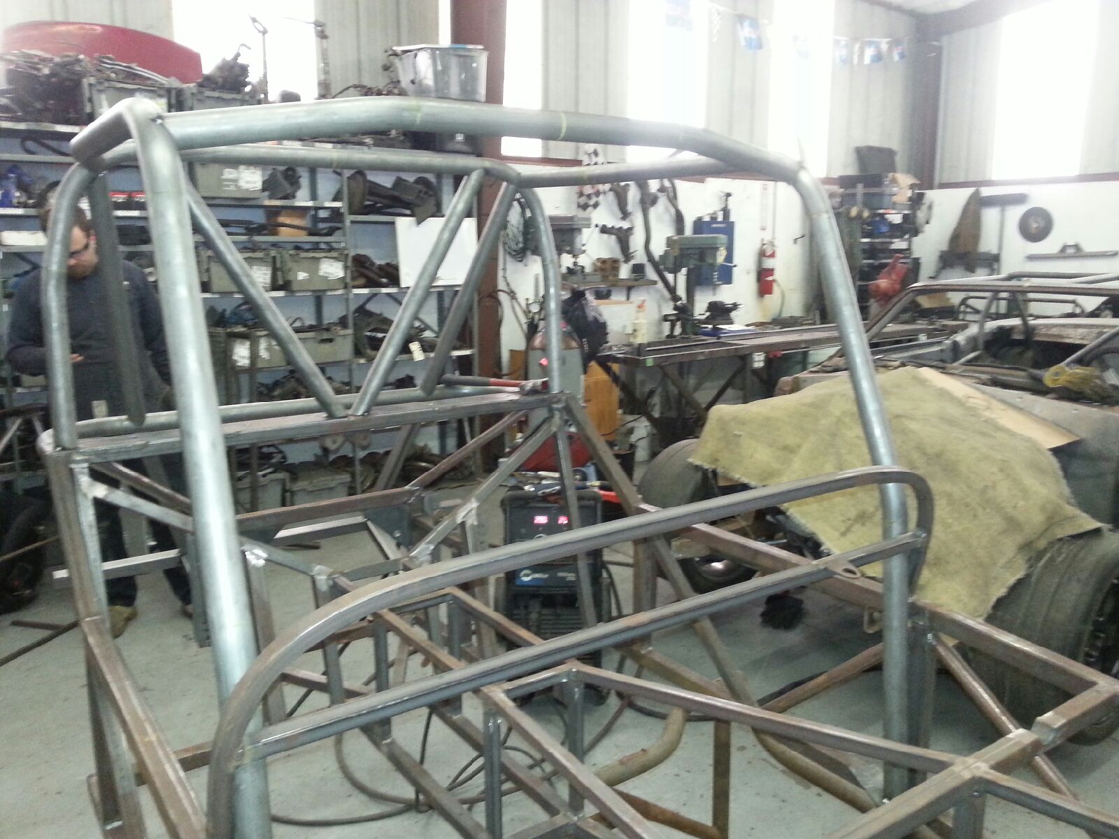
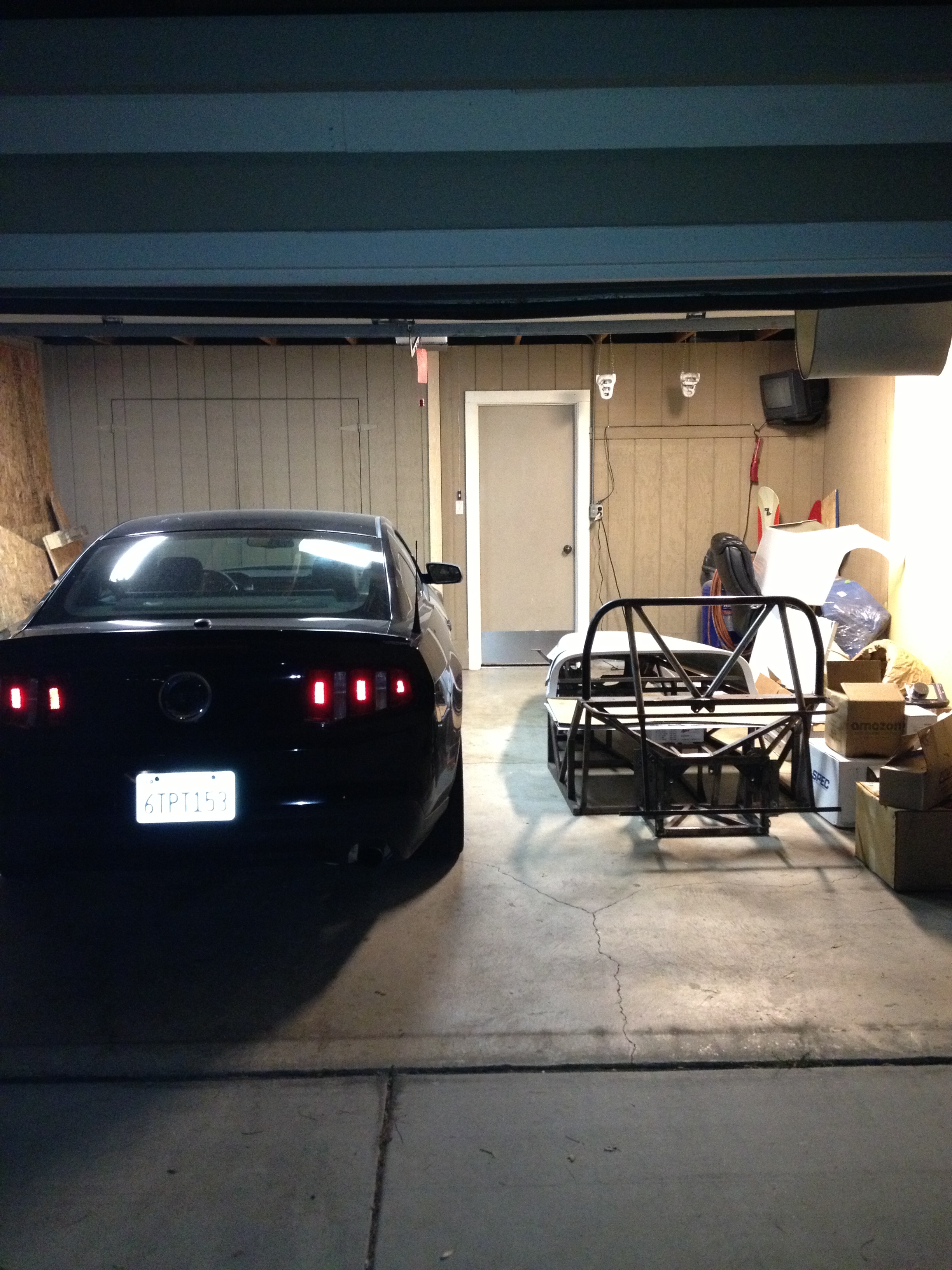
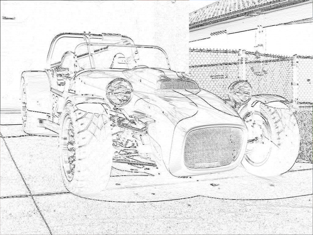
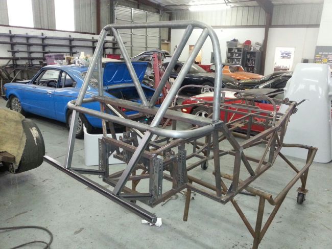
Around this time, Evil Genius Racing got back to me with a mocked up roll cage design, which you can see the back half of here.
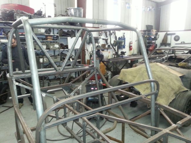
Image


And the front here.

Image


The big news here, is that the guys over at Targa Newfoundland have also been involved in this cage design, and have approved the car(at least as far as concerns safety and classification) to be raced next year in the Targa Open class. There is still a lot of work for me to do to actually get there, including getting a competition/racing license and first aid certificate, but this an event I am massively excited about.

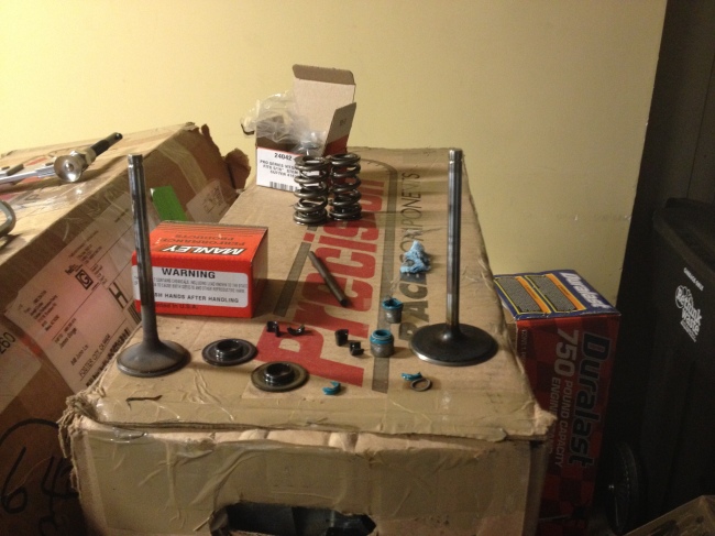
Finally, the remaining valvetrain components arrived, and we’re back to replacing valvesprings on the heads. Once I acquired the new spring seats, I discovered they would not fit over the current valve stem seals. This meant I would need to replace the valve stem seals, since they cannot be removed without destroying them. It took me significant effort to get the old ones off of there, I tried pliers at first, channel locks second, where I was able to pick the head up by just a valve stem, and finally a 3 pound slide hammer with a seal puller attachment did the trick.

Image


I ordered in some new valve stem seals, since the factory GM ones include a spring seat that is not suitable for my springs. The new seals proved to be about half as difficult to put on as the old ones were to get off, and it took me ruining a rocker arm bolt to figure out the best way of putting them on. Here that process is, in the form of a picture.

Image


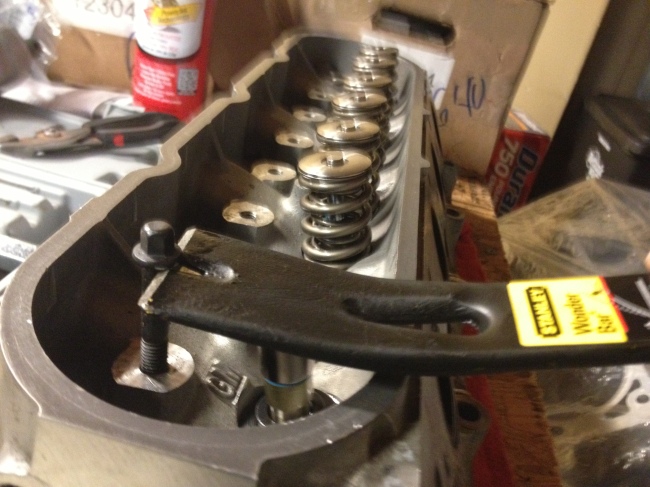
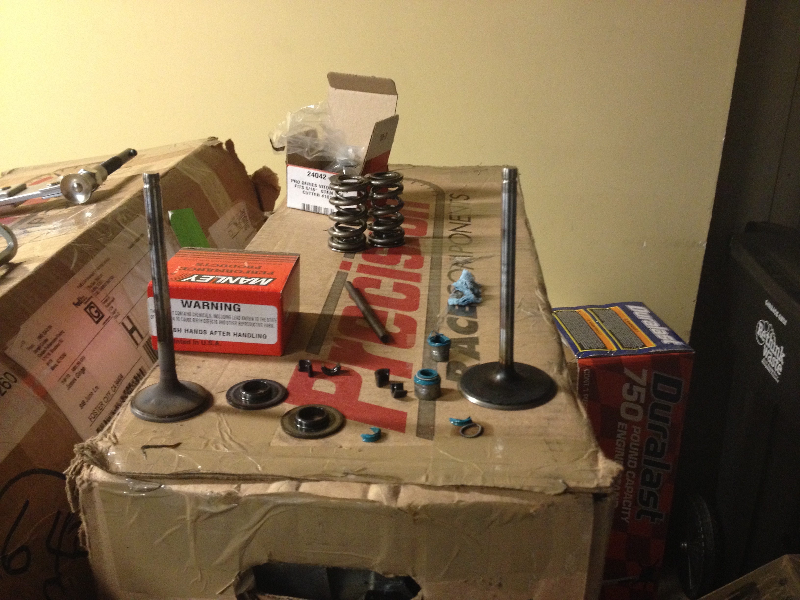
I actually found that flipping the pry bar over provided the best leverage, but did not take a picture of that. And here is a shot of nearly everything you need for one cylinder, destroyed old valve stem seals included.

Image


Here we have a picture of the retaining collars that hold the locks onto the valves, which keeps the springs contained.

Image


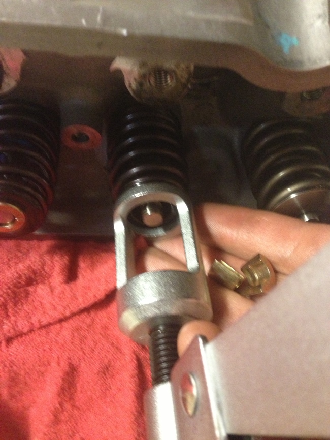
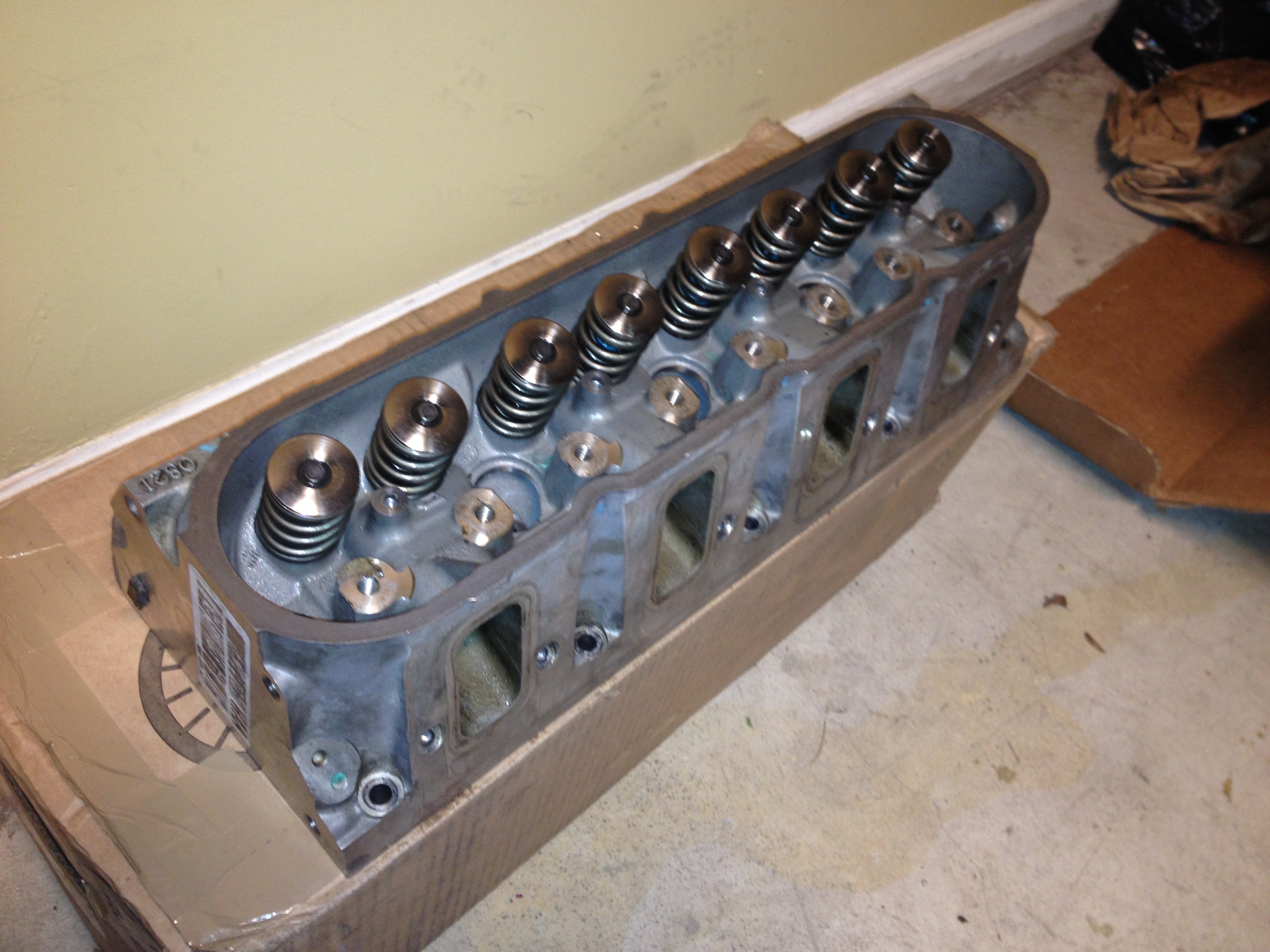
Sorry that one is a bit blurry. On the left you can see one of the new springs completely installed, and on the right you can see one of the old ones still there. Once finished with this job, I did find out that the rocker arms sit across these retainers, since the valve is depressed within them, and so I’ll need to get new retainers and do this all over again!

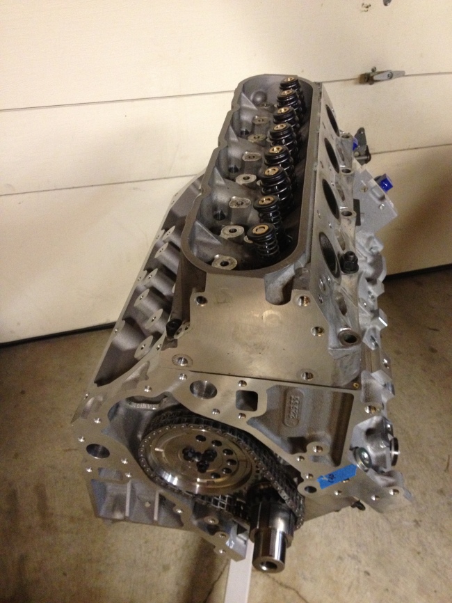
Finally, after all of that, I put some testing springs on for cylinder one, and began to check the piston-to-valve clearance. It was nice to see the head on the block, to test fit with the head studs, install my new fake solid lifters, and install the new aluminum rocker arms to test the clearance. It almost looked like an actual engine with everything temporarily bolted on! The clearance turned out fine, and all I got was this one picture of that whole process.

Image


And now, as I writing this very long post that I should’ve broken up across several weeks, the actual hydraulic lifters that will be going in the engine are cleaned, and sitting in fresh engine oil to soak a bit.

As always, there is more work to come!

Now With Color!

Over last weekend, I tried again to wrap one of the wheel covers with a vinyl wrap. I once again got frustrated, turning the wrap into a ball of orange and adhesive and throwing it away, and decided to try my hand at painting! So I went out and bought a spray gun, some paint, a “satin” clear coat, and a whole bunch of plastic and masking tape.

I started by making a tent in my garage to spray panels in:

Image


Inside, it ended up looking like a scene from Dexter:

Image


I washed and prepped the surface of the first wheel cover, seen above, by scratching the existing sealer finish with a wet scotch-brite pad,  and then dried it off. I then thinned the base/color paint, and set the spray gun up to spray the relatively thin paint on. The first attempt did not go so well, apparently the sealer on all the fiberglass parts is a lot tougher than I expected. You can see in this picture how the paint pulls back from some areas, and pools up in others.

Image


Seeing this, I decided to re-prep this particular panel. I scrubbed it again to remove any still-wet paint, and then sanded it lightly with wet 600 grit sandpaper. Once the surface was smooth again, I once again scratched it up using a scotch-brite pad, this time with a bit more force. Once finished, I wiped the whole thing down with a tack cloth to remove any remaining dust or paint particles, and was ready to try painting again.

Image


This prep was far better than previously, and after a few coats this panel’s base color layer turned out quite well, despite me still learning how to spray effectively.

Image

I did still end up with one low spot and one run near the shoulder, and so I got ready to wet sand that area a bit once it had dried enough. In the mean time, I prepped the remaining 3 wheel cover/fender panels, and mixed more of the orange paint. From this point, the color layer went fairly quickly, with only one more paint run on the second panel I sprayed, and the last two coming out as well as I could’ve hoped for.

Image

Once every panel was ready for the final coat, I spent a few minutes cleaning up the two problem areas with wet 600 grit sandpaper on a block. Once the paint was smooth again, and without going all the way through, I ran a tack cloth over those two panels and gave the sanded areas a very light coat of paint to finish them up.

Image


Now I had to let the base coat dry a bit, clean the spray gun, mix the clear coat with it’s activator, and prepare to spray 2 coats of clear on each panel. The inside of the garage was getting quite hazy by now, and the temperature was dropping as the humidity was rising, making it more and more difficult to properly spray the clear coat. I ended up having some issues with “orange peel” on the final clear coat, and will need to work on cleaning that up once all the paint has had a chance to cure/dry at least 24 hours. I should be able to clean it up using wet 2000 grit sandpaper on a block to knock down the higher areas, without needing to apply any more clear coat.

I’m pretty happy with the final result:

Image

They turned out better than I expected for my first time trying. Three of the panels are slightly damaged from shipping, but I expect they will take more abuse while I continue to build the car and during the initial test drives. Once the car is running reliably, I plan to sand all the panels down, patch up any fiberglass damage, and re-paint them.

It ended up being a very long day, almost 8 hours of solid paint work when I expected to be done in 4. This is definitely something I want to continue working on, and getting better at, since I ended up enjoying it quite a bit. I also took a jumpsuit/face mask selfie before getting started:

Image

And once I was able to remove the mask, I was extremely glad I had had it on the whole time:

Image


In other news, most of the remaining engine parts are with UPS right now, and I expect them all to have arrived by the middle of next week. I’m excited to get the engine to a very nearly runnable point, and first start up shouldn’t be too far off now!

Short Block Assembled

Today, with a lot of help from Bobby, I was able to get the car over to Evil Genius Racing to get a full roll cage put on. With a proper roll cage, and some additional bracing and anti-intrusion bars around the passenger compartment, the car will meet the safety requirements for many more events than previously. They will also be powder coating the frame and suspension components, so when I get it back I will be able to start putting more of the car together.

In the mean time, I had the engine to build, and last weekend I finished filing piston rings, and began assembling the short block itself.

Image

Unfortunately, one of the connecting rod bearings I had had a manufacturing defect, and I wasn’t able to put all 8 cylinders together.Image

So, I ordered a replacement, as well as a new piston ring compressor. The ring compressor I had been using was taking about 5-10 minutes per cylinder, and was a lot of difficult work. Today, with the new one, that step was taking only about 1 minute per cylinder. I installed the final rod bearings, and then finished assembling the short block.Image

With that done, I need to get a cam, pushrods, and head gaskets, and I will be able to assemble the long block. From there, I will need more of the external engine components, like the sensors, oil pan and pump, timing gear and chain, and the serpentine belt system to have a runnable engine.

So far, I have roughly 25 hours of labor into this short block, a good part of that has been learning how to do just about everything done so far. Things are a little more familiar to me from this point on, and hopefully I’ll be able to make faster progress. Can’t wait to get this engine started and see what it can do!

Finally, some actual work!

This week, I finally managed to get main bearings sized up and ordered. This means I have nearly everything I need to complete the short block assembly, at least as far as the rotating assembly. And so, I began putting together pistons with connecting rods.

Engine construction site alpha:

Image


Putting the clips that hold the wrist pins in was proving to be difficult and painful. They are wire locks, essentially circlips without the bend that allow pliers to compress them. After 2 hours of experimentation, I discovered the best way to install them was to bend them sideways to look like a spring coil, and then lever them into position using a jeweler’s screwdriver.

At this point I moved on to engine construction site bravo:

Image

Once I figured the wire locks out, it took an additional hour to assemble all 8 pistons with connecting rods(no piston rings yet, since the wrist pins would not be able to be slid into position with the rings in place).

Image

The next step from here, since I could not easily turn the block over by myself, was to start filing piston rings to have the piston ring gaps sized properly.

So on to construction site charlie:

Image


I spent some time checking the gaps on the oil ring support rail, the oil rings and oil spacer, which were all gapped properly straight out of the box for cylinder 1. Next up was the second compression ring, since I need to work from the bottom of the piston up. The second rings I have are napier rings, and you can see what that means here in this image I borrowed from Google:

Image

The second rings are also fairly soft and workable, and so I was able to file the ends to make the proper gap within about 30 minutes, checking very frequently as I’d never done this before.

The top rings on the other hand, are extremely tough and nearly impossible to work with a hand file. They are the “barrel face” design from the chart. I ended up having to use an air powered rotary tool with a small grinding wheel to make any noticeable changes, and even then it ended up taking me an additional hour to get the top ring gapped properly for cylinder number one. I called it a night for Saturday at that point.

On Sunday I went looking for a ring file that would let me cut the rings down a bit faster, but came up empty. What I did find was a well priced engine stand, and so with some help I got the engine block mounted on a taller stand that can rotate the engine easily. Since continuing to work on the pistons would be inefficient until I get a ring file, we decided to put the crank into the block instead.

Scott, Var and I spent some time removing the main caps and cleaning up the bearing lands and threads. Then, we installed the main bearings, crankshaft, and reinstalled and torqued the main caps(mostly):

Image

Since it turns out I’m missing the M8 bolts that go in the side of the main caps, we’re done for now. Fortunately those can be installed last, and torqued last, so we can let it sit as it is for now. Before I can continue I’ll need to get those bolts and torque them down, and then I can move back on to fitting the piston rings, and finally the pistons themselves into the engine block.

Overall, some of the tasks I thought would be fairly simple ended up being a lot of tedious work, and I expect that will continue. On the other hand, I’m happy to have been able to make some progress on the build. Looking forward to getting to put the rest of the rotating assembly together in the block, before I make more decisions about new parts.

It’s Finally Here!

After dealing with a lot of shipping shenanigans, the main kit is finally here!

IMG_0404


The crate was a bit of a mess, and had been “repaired” a couple of times in transit apparently. Big thanks to Var for helping me get it home anyways. After a couple hours of unloading and dismantling, most of the car was in my garage, and just the frame itself was left to unload.IMG_0408

With a little more help from Var and Ted, we got the frame into the garage as well, alongside the other car.

IMG_0409


The next step is to get the frame sand blasted and powder coated, to prevent it from rusting and make it look awesome. While I’m doing that, most of the engine is at http://www.robsautomachine.com/, getting the cylinders honed, and the rotating assembly balanced. I should be getting that all back in the next week or so, and then I can build most of the engine itself.

Besides the rotating assembly, which I neglected to take pictures of before handing off for balancing, the roller rockers also arrived. They are slightly higher ratio than stock, so I can run a fairly mild cam and keep the valve train solid and reliable:

IMG_0410


Still a whole bunch of hardware and gaskets to buy for the engine, and a transmission, differential, seats and wheels for the rest of the car. Now to find a way to get the frame to a shop for coating.

Parts Accumulation

More parts are coming in, and I almost have something to do besides shop. I was able to pick up a set of ARP head studs, and a pair of used LS3 heads with PAC 1208 double valve springs:

Image

These will be just about perfect for this engine, but I may sell these springs to go with a slightly lighter “beehive” single spring design, since I don’t intend to run a very aggressive camshaft. The threaded holes just beside the springs are for stud-mounted rocker arms in the stock engine, but I’ll be going with a slightly sturdier semi-shaft mounted design to stabilize the arms, especially at higher RPMs.

I also picked up a new stock LS3 intake manifold, and a 90mm electric throttle body:Image

This stock air intake setup should be plenty for the power levels I’m shooting for here. I’m waiting to pick up fuel injectors and fuel rails until I select a cam, so I can be a little more accurate with the sizing of the injectors.

I also have a steering wheel with a quick release steering hub, and a steering u-joint. That should be everything I need(besides wheels and tires) to make the car roll and steer once the chassis and bodywork comes in, which will be extremely helpful to make room in the garage while I finish the engine.

The engine block itself has minor surface stains in the cylinder bores from being stored unsealed before I bought it, so I’ve decided to have it honed out to 4.070″ to clean that up, just to be safe. The actual engine assembly is still a ways off, some parts are backordered, some are custom order, and I am still deciding what exactly I want.

Still a very engineering heavy update, soon I hope these are a little more entertaining. The kit itself is shipping this week, and once that arrives some of the work can finally start!

Project Introduction

sobel_stalker

For years I’ve wanted to build a car. I’ve tried my hand at a couple of restoration projects, which have never gone very well. A few times I’ve tried to keep an older, unreliable, British or Italian car running, never with very much success. Despite those frustrations, I’ve always enjoyed working on cars, and I’ve missed it very much lately. Thankfully I now have an opportunity to start a new project, and here is what I’ve decided to do: build a Brunton Auto Classic R kit car. The kit will normally accept either an L32 Buick Supercharged V6 engine, or in my case, a Chevy LS3 V8, most commonly seen in the 2008+ Corvette. So, the high level specs:

  • Weight: 1460lbs
  • Power: 430hp@5900RPM, 424lb/ft@4600RPM
  • Displacement: 6.2L/376ci, all aluminum
  • Transmission: 6 speed manual T-56
  • Suspension: 4 wheel independent, double wishbone with pushrod actuated inboard coilovers.
  • Wheels/Tires/Brakes: 17×9 wheels, 275/40R17 Toyo R888 tires, 12.75″ disc brakes with Wilwood 4 piston calipers

I’ve decided that while I’m waiting for the bulk of the chassis and body parts,  this would be a great time for me to learn more about engine internals. To do that, I’m building the engine myself from a bare block:

ls3_block

I’ve also got pre-assembled, lightly used aluminum LS3 heads on the way, which I will be taking apart and rebuilding before fitting to the short block.

Not much more to report until more parts start arriving. The chassis, suspension, brakes, and body work should arrive in early October. By mid-September most of the engine components should be here. In the mean time I’ve been reading http://www.amazon.com/Modify-LS-Series-Engines-Motorbooks-Workshop/dp/0760335435/ref=sr_1_1?ie=UTF8&qid=1376800971&sr=8-1&keywords=how+to+build+and+modify+gm+ls-series+engines. I’ll also be keeping a cost log, but won’t be sharing that until much nearer the end of the project.

This is absolutely the most ambitious project I’ve ever undertaken, and I can’t wait to get properly started.