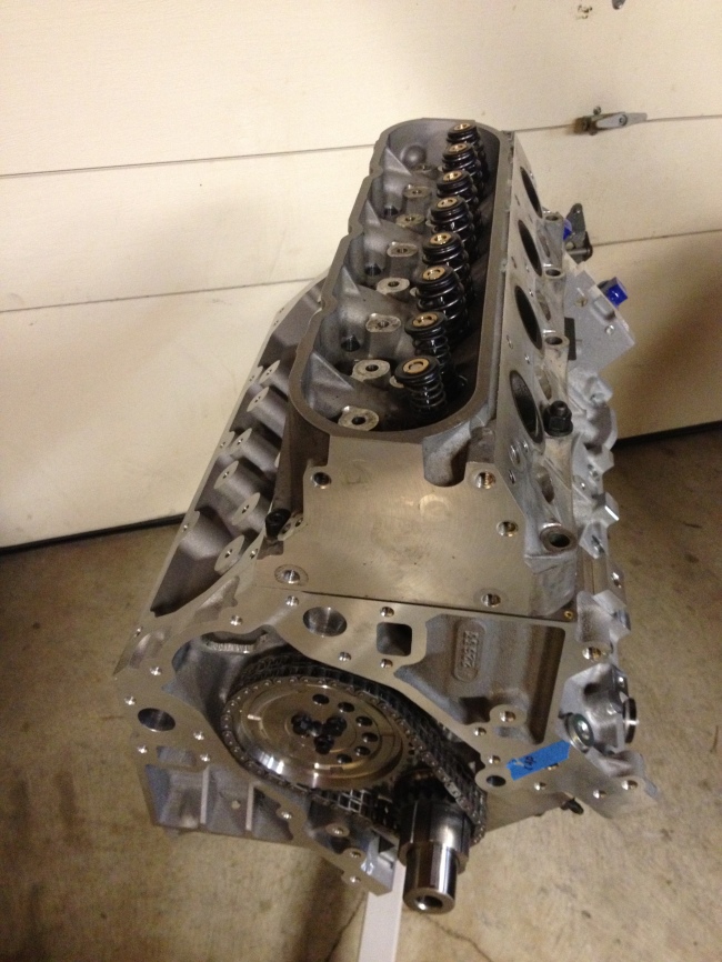
Over the past few weeks I’ve been making very incremental progress on the engine build, trying to scrounge up all of the various small pieces and tools required. At this point it probably would’ve been worth my time to go buy a junked engine just to use for various bolts, spacers, and whatever else rather than wait a few days at a time for the next part I need. Diving right in to the details and photos for that, here we go.
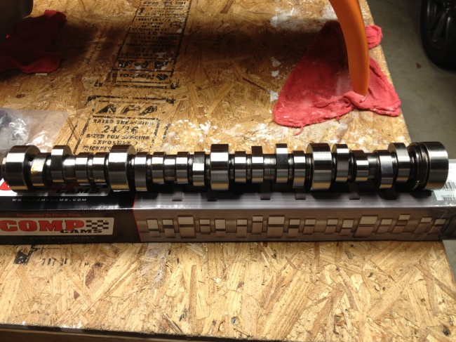
We start with the cam:
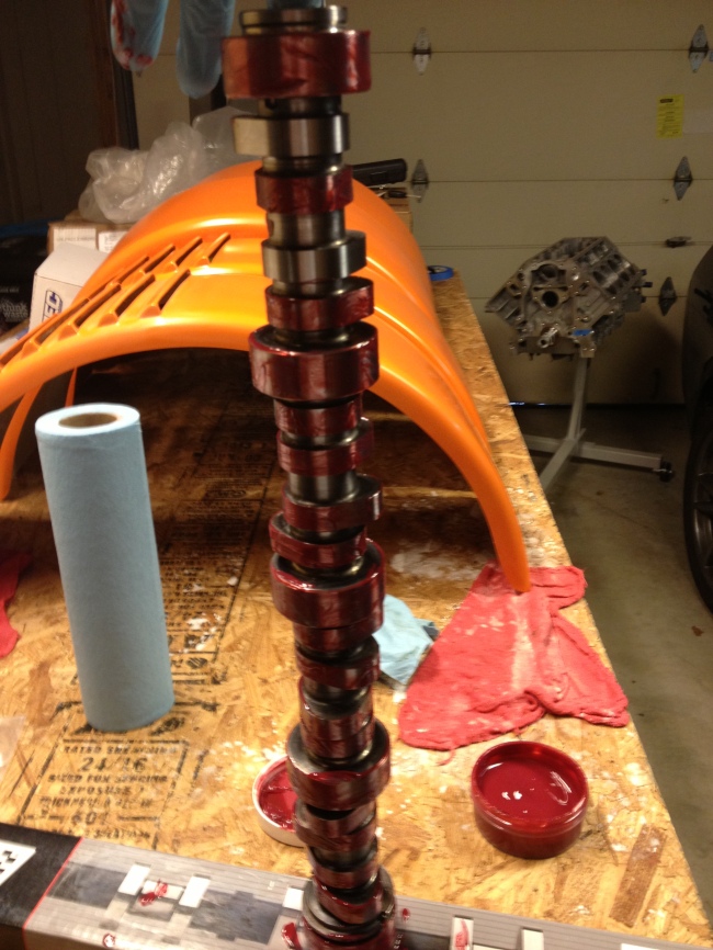
This is a relatively mild cam, only providing about 0.55″ of valve lift in a stock set up. My valvetrain being what it is, this ends up about 10% higher, and it should make for some pretty decent high-RPM power. The first step was to clean and grease the cam lobes, leaving #1 and #3 clean for use in testing Piston-to-Valve clearance later.
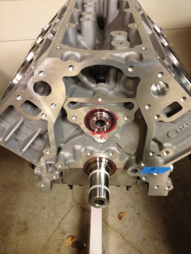
Next up, very gently the camshaft was placed in the engine, to wind up sitting on the camshaft bearings.
At this point one of my delays took place, while I ordered a cam thrust plate and bolts that I had assumed were part of the front main cover kit I had. I decided since I was making an order to go ahead and get the oil pan, windage tray, oil dipstick, head gaskets, and a camshaft degree checking kit as well. I ended up with a Holley oil pan with internal baffles that should be adequate for prevent oil starvation while cornering. Unfortunately the vendor I would’ve preferred to use doesn’t sell a suitable oil pan, but this will do nicely.
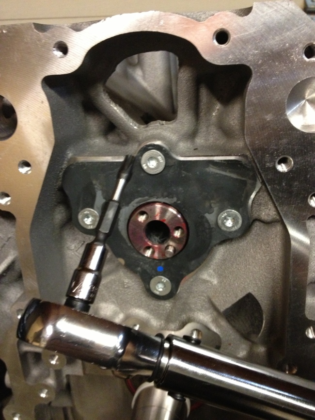
Once I got the order in, I continued by bolting down the cam. I was a bit surprised to find that these bolts required a T40 bit, and I had to dig around for quite a while to find one.
Next up, I started working on replacing the valvesprings in the heads. The heads came to me with about 800 miles on them, with some nice aftermarket double springs, but I want to try and keep the valvetrain as light as possible, and with the added stroke in the crankshaft won’t be turning this thing much faster than a stock one would anyways. So I replaced the existing springs with some high rate single beehive springs.
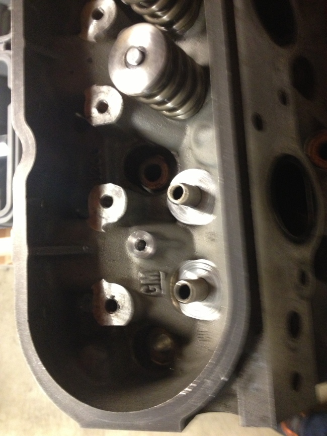
At first I thought this would be a simple matter of just swapping the springs using a spring compressor. In this picture you can see one of the old springs removed, and the spring seat it was sitting on.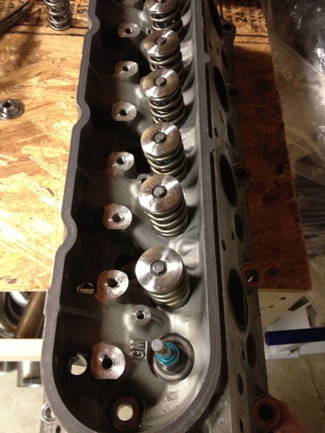
These seats turned out to be a problem, as well as the locks and retainers. I ordered all new valvespring hardware once I realized this, except for valve stem seals(that teal bit in the picture above), and put the valvespring project on hold until those arrived again.
In the mean time, I got all of the block coolant plugs and the oil restrictor, and put those in the block. One of the main coolant plugs takes a 17mm Allen wrench to turn, which no hardware store stocks, and so I was stuck on this front until one arrived as well.
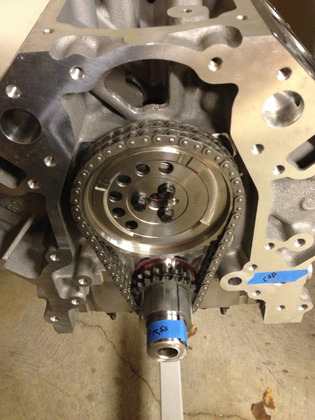
Being stuck now on two projects, I moved on to the timing set for the cam, and the timing gear and oil pump gear on the crankshaft.
The timing set is a Comp Cams adjustable double timing set, and it was quite a pain to install. As you can see in the picture there, I had a note to myself to one day finish pressing the gears onto the crankshaft. These gears can’t be pounded on with a hammer, since the crankshaft itself sits directly on the main bearings. I ended up buying 3 different length bolts, a stack of various sizes of washers, some 1-1/2″ electrical conduit, and a 2″ diameter section of steel pipe to get them pressed all the way on. It was basically like playing stackable pipe Tetris, except each turn you have to unbolt a giant bolt.
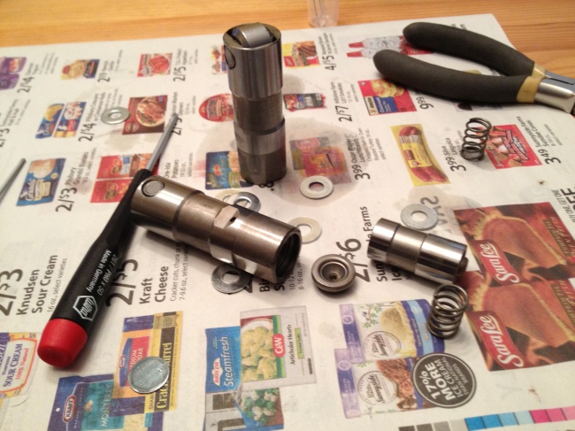
That thankfully accomplished, I needed to be able to check the camshaft timing and the piston-to-valve clearance, so I converted some cheap hydraulic lifters into solid lifters to measure with.
To do this, start by removing the retaining clip/spring(it helps if you aim this at your eyes and don’t wear protective glasses). Next, remove the plunger, seen here on the right, and spill all the oil on yourself. Finally, replace the plunger, add a washer or two as a spacer, leave the spring out, and put the retaining clip you shot at yourself earlier back in, if you can find it.
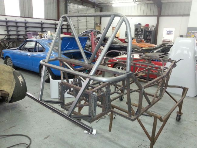
Around this time, Evil Genius Racing got back to me with a mocked up roll cage design, which you can see the back half of here.
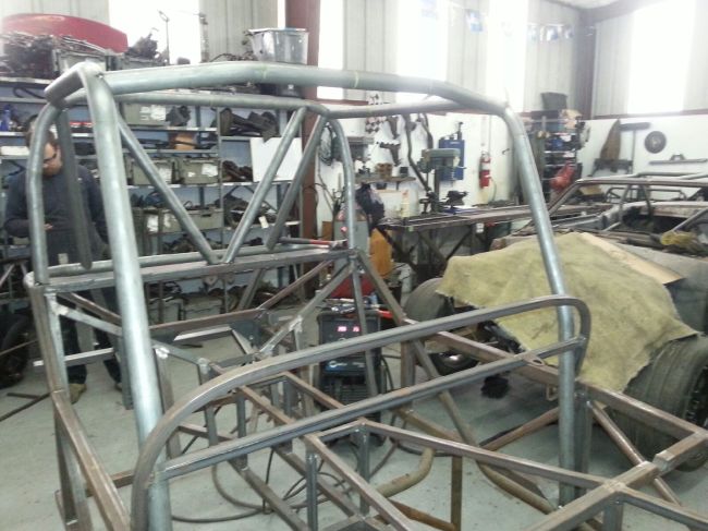
And the front here.
The big news here, is that the guys over at Targa Newfoundland have also been involved in this cage design, and have approved the car(at least as far as concerns safety and classification) to be raced next year in the Targa Open class. There is still a lot of work for me to do to actually get there, including getting a competition/racing license and first aid certificate, but this an event I am massively excited about.
Finally, the remaining valvetrain components arrived, and we’re back to replacing valvesprings on the heads. Once I acquired the new spring seats, I discovered they would not fit over the current valve stem seals. This meant I would need to replace the valve stem seals, since they cannot be removed without destroying them. It took me significant effort to get the old ones off of there, I tried pliers at first, channel locks second, where I was able to pick the head up by just a valve stem, and finally a 3 pound slide hammer with a seal puller attachment did the trick.
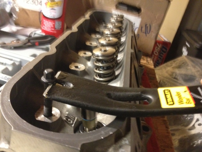
I ordered in some new valve stem seals, since the factory GM ones include a spring seat that is not suitable for my springs. The new seals proved to be about half as difficult to put on as the old ones were to get off, and it took me ruining a rocker arm bolt to figure out the best way of putting them on. Here that process is, in the form of a picture.
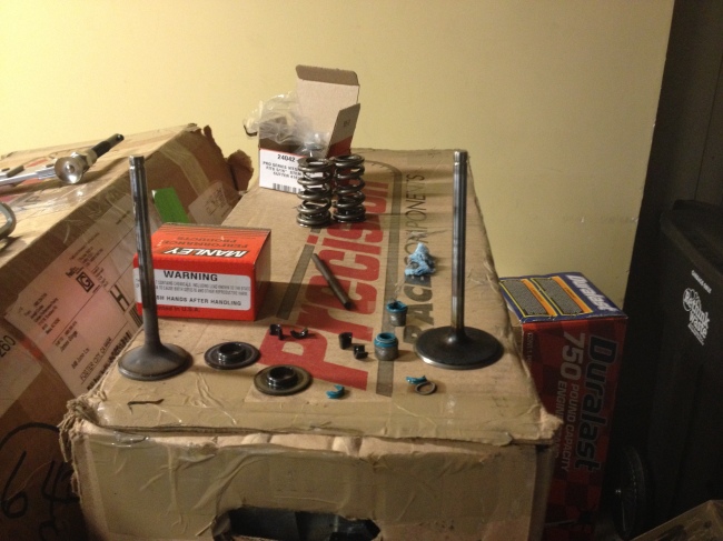
I actually found that flipping the pry bar over provided the best leverage, but did not take a picture of that. And here is a shot of nearly everything you need for one cylinder, destroyed old valve stem seals included.
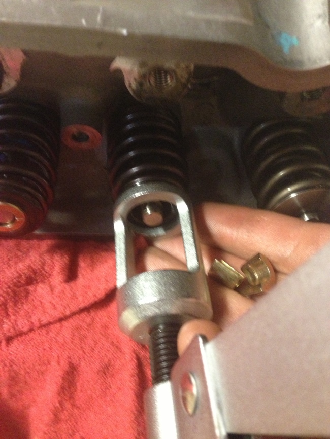
Here we have a picture of the retaining collars that hold the locks onto the valves, which keeps the springs contained.
Sorry that one is a bit blurry. On the left you can see one of the new springs completely installed, and on the right you can see one of the old ones still there. Once finished with this job, I did find out that the rocker arms sit across these retainers, since the valve is depressed within them, and so I’ll need to get new retainers and do this all over again!
Finally, after all of that, I put some testing springs on for cylinder one, and began to check the piston-to-valve clearance. It was nice to see the head on the block, to test fit with the head studs, install my new fake solid lifters, and install the new aluminum rocker arms to test the clearance. It almost looked like an actual engine with everything temporarily bolted on! The clearance turned out fine, and all I got was this one picture of that whole process.
And now, as I writing this very long post that I should’ve broken up across several weeks, the actual hydraulic lifters that will be going in the engine are cleaned, and sitting in fresh engine oil to soak a bit.
As always, there is more work to come!
